After five years and a few prototype revisions of the Version 2.12 Programmable Voltage reference, I decided it was time to update the project based on many requests and lessons learned from prototypes over the years.
A year after completion of the version 2.12 programmable voltage reference (PVR), in 2017 I built another prototype unit based on a Maxim MAX6341 4.096 volt reference. It included a dedicated ‑5 volt supply, and a MAX6126 2.048 volt reference for the Teensy 3.2 board. There were dedicated headers for the serial port and front panel buttons. It was later updated with an inline I2C EEPROM board in 2018, which allowed each millivolt step to have it’s own calibration storage position.
The project remained dormant for several years while I worked on many other projects. After many requests for a 5 volt version of the PVR, I started working on an updated design again last year (2021) at a slow pace. The two main design factors were, providing an output up to 5 volts, and reducing the drift at the output from temperature and humidity changes.
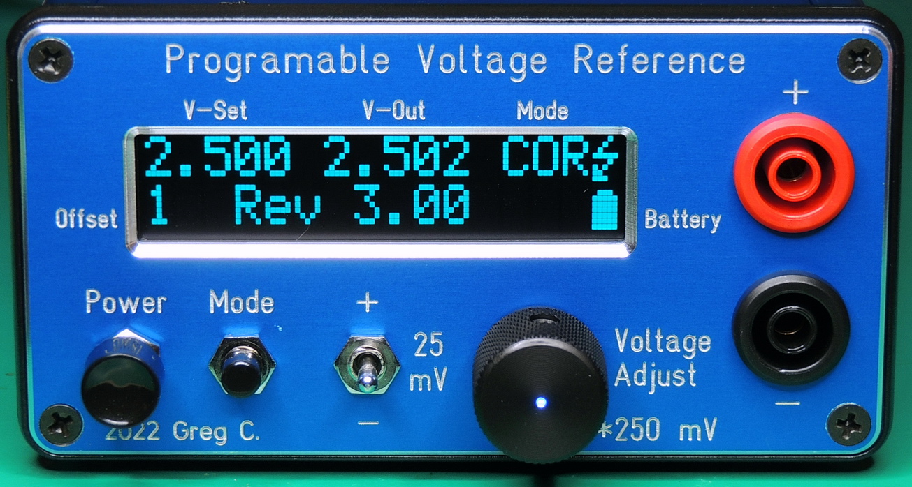
What I ended up with after many iterations, was a 0.001 to 5.000 volt output version 3.14 of the Programmable Voltage Reference, with new components and and upgraded specifications.
Where to start, as there are so many changes in this version, and so many thing that remain the same.
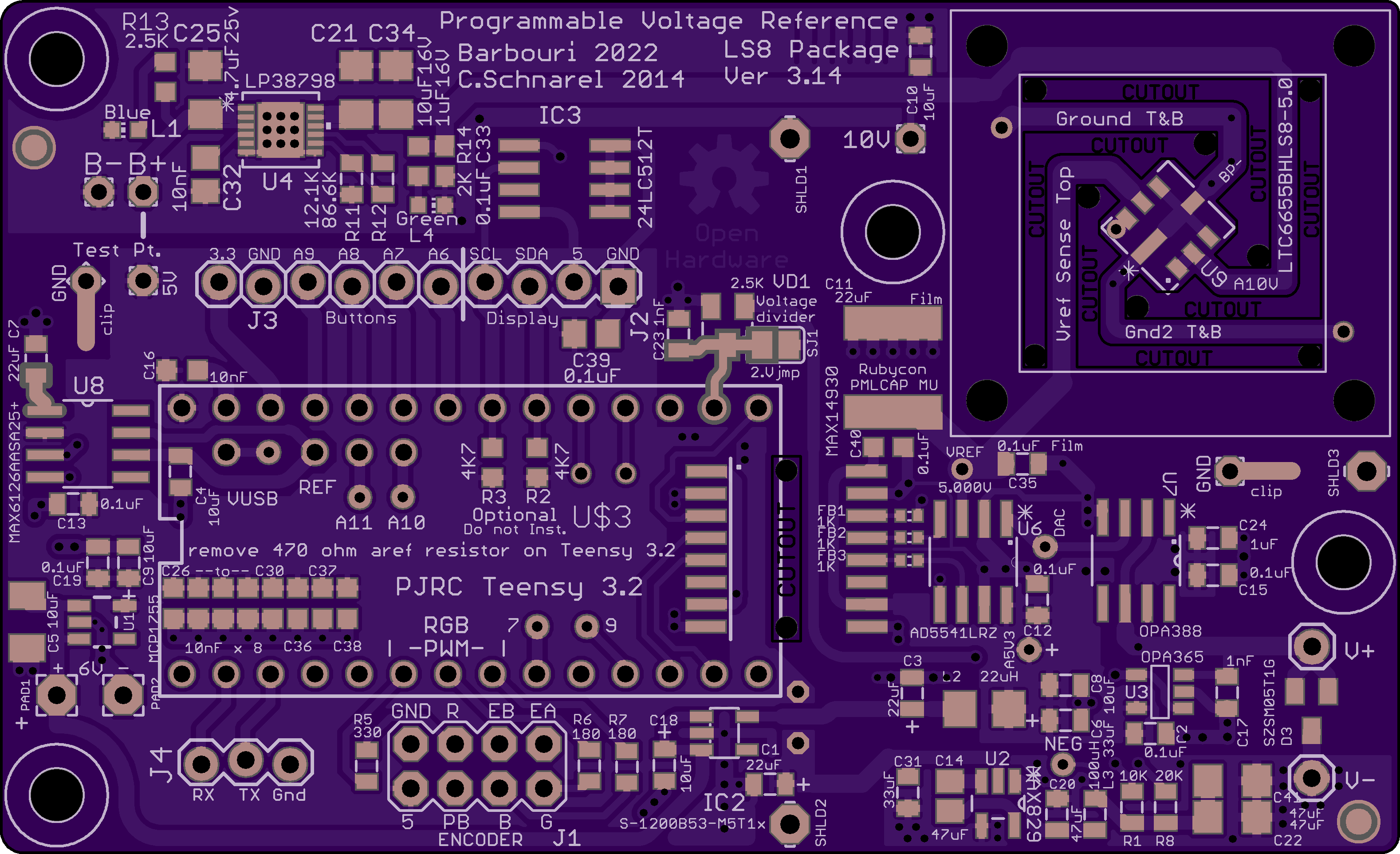
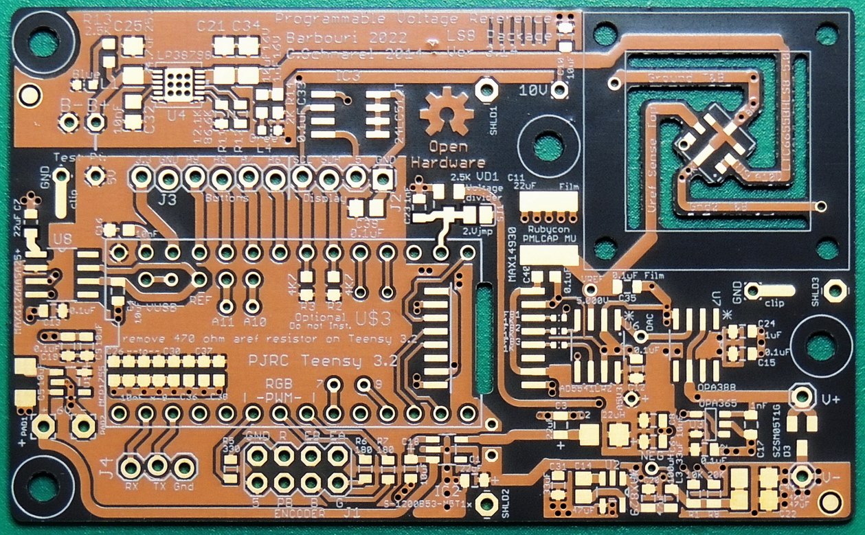
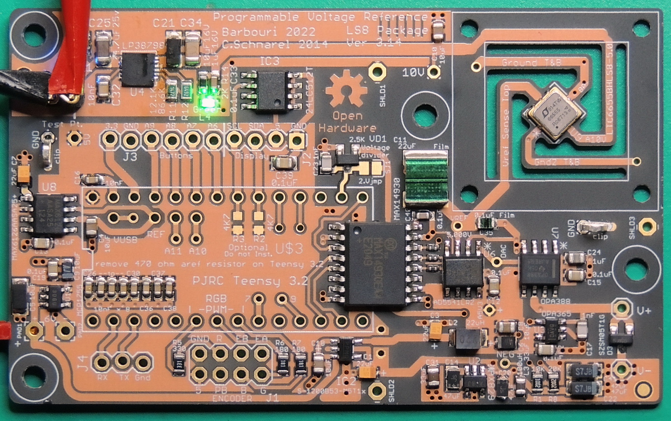
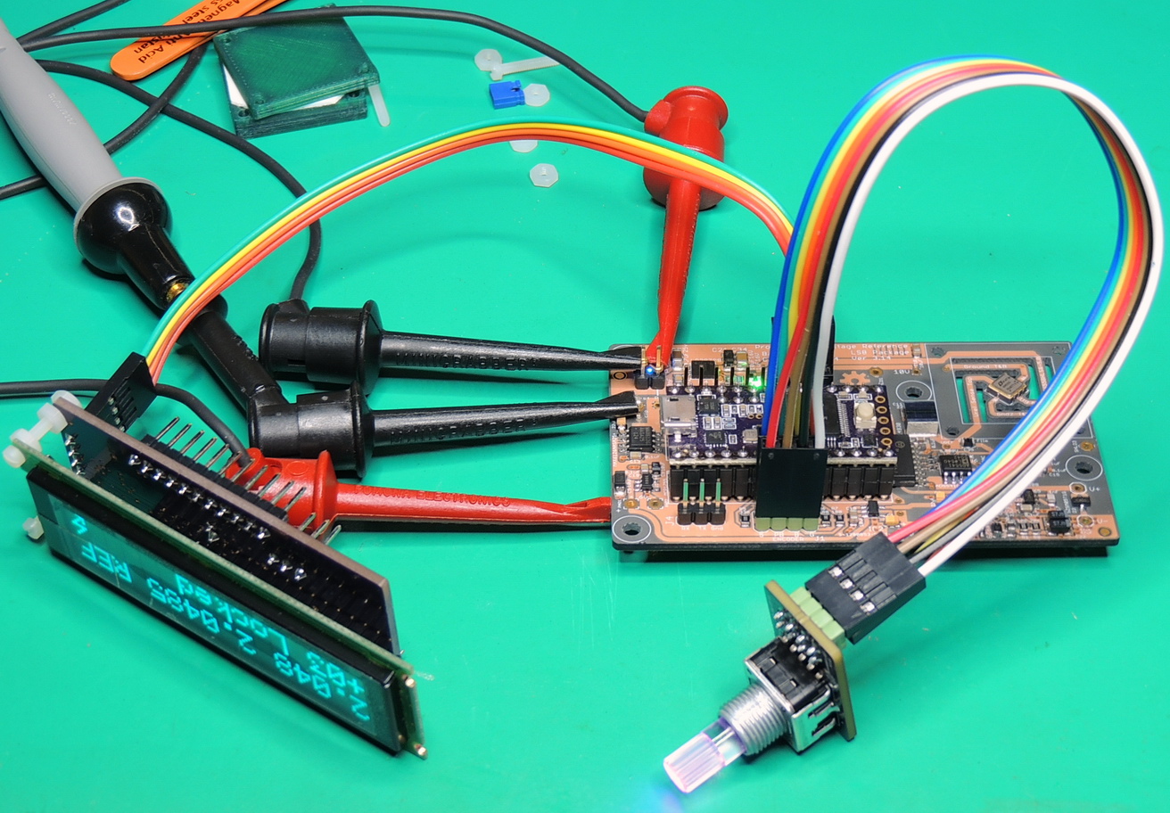
The most obvious change is the LTC6655BH-LS8 5 volt bandgap reference IC from Analog Devices Inc., situated in it’s own special section of the board.
I chose the LS8 package which is a 5mm × 5mm surface mount hermetically sealed unit that provides outstanding stability and no humidity sensitivity. The BH units have a datasheet specification of less than 2ppm/°C and an output voltage accurate to ±0.025%.
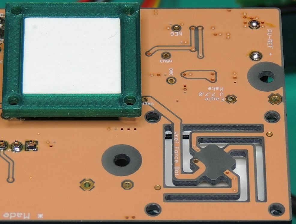
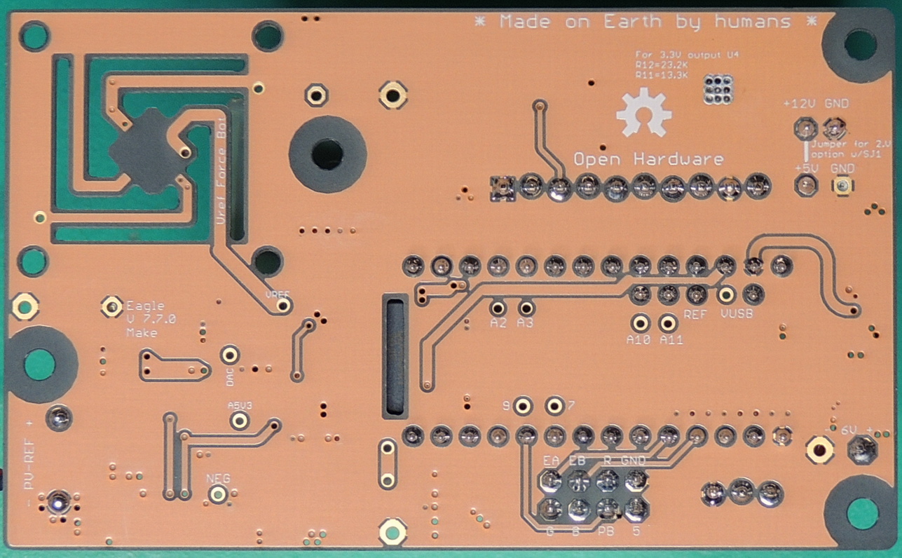
The circuit board is routed out around the reference IC footprint, in what I call spider legs. There are four traces on top and four traces on the bottom for 8 legs. The LTC6655 has force and sense connections that utilize the top and bottom traces on one of the legs, which tie together near the reference input on the DAC IC. There is a mounting area outside of the spider legs for a 3D printed enclosure to reduce air currents, and provide thermal stability for the reference IC.
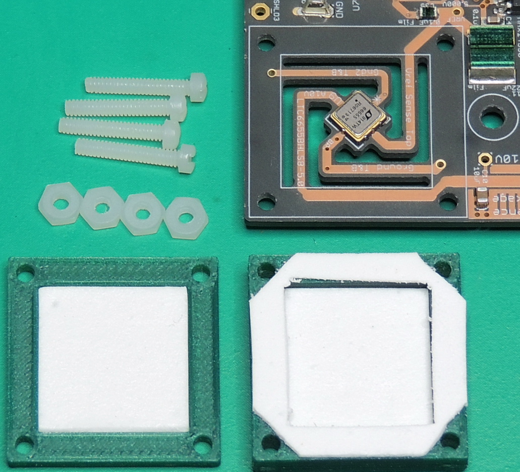
The 3D printed reference enclosure uses several layers of roVa Flex Plus Aerogel Insulation on the front and back housings for increased thermal resistance. The housing is attached with four nylon fillister head 2–56 X 1/2″ screws.
The output filtering capacitors for the LTC6655 reference consists of two Rubycon film ML series capacitors with values of 22 uF and 0.1 uF placed close to the reference and D to A converter IC.
Another change is the Analog Devices Inc. AD5541LRZ 16 bit unbuffered DAC in a 8‑SOIC package. The AD5541 features a 1 µs settling time, low noise performance of 11.8 nV/√Hz, and 1 LSB INL accuracy at 16 bits without adjustment. It is also much easier to solder than the previous AD5060BRJZ in the SOT-23–8 package. I included some tiny 0402 signal line ferrite bead inductors on the SPI lines connected to the DAC after the MAX14930 isolator to reduce digital noise.
The Teensy 3.2 external voltage reference IC changed from a Maxim MAX6126 2.048 volt unit to a MAX6126 2.500 volt version. This keeps the Teensy’s ADC reading 1/2 the output voltage value.
The DAC output buffer op-amp has changed from the LTC1152 to a Texas Instruments OPA388 which features ultra-low noise, fast-settling, zero-drift, and rail-to-rail input and output operation.
Because we are using a 5 volt reference, the analog power rail was increased to 5.3 volts, and is supplied by voltage regulator IC2 which is an ABLIC Inc. S‑1200B53.
The original 2.12 PVR used a digital output from the microprocessor to generate a negative voltage rail, and now uses a Maxim MAX829 switched-capacitor voltage inverter for the ‑5 volt supply.
To power the new 5 volt reference IC, I used a Texas Instruments LP38798 800-mA Ultra-Low-Noise, High-PSRR LDO regulator. It is set to 6.4 volts using resistors R11 and R12, which values are labeled incorrectly on the Ver. 3.14 board. They should be labeled 14.7K and 64.9K Ohms respectively, and have been updated in the Ver 3.15 schematic.
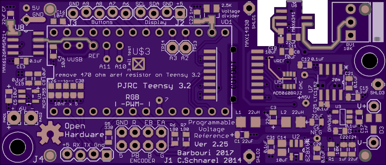
You may have noticed by now that the circuit board is not my standard OSH Park purple soldermask version. I decided to try out OSH Park’s “AfterDark” fabrication service that uses a clear soldermask on a black substrate. I was very happy with the quality of the boards, the clear soldermask gives the black substrate a matte dark grey look, which is fine for my application because I was mainly interested in showing off the copper. By removing the soldermask from areas in the board design it will provide an even darker black look if needed.
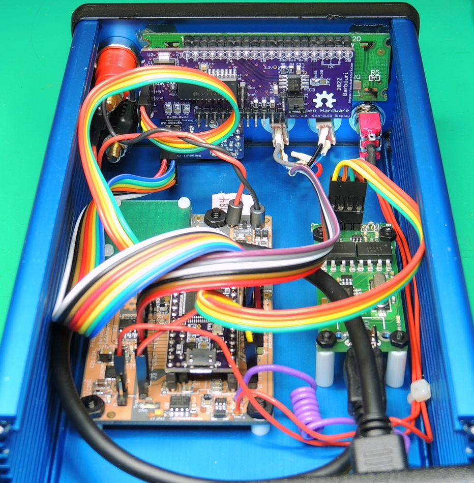
The PVR still uses a PJRC Teensy 3.2 (purple edition) microprocessor and requires the removal of the 470 ohm aref resistor, to use the external voltage reference.
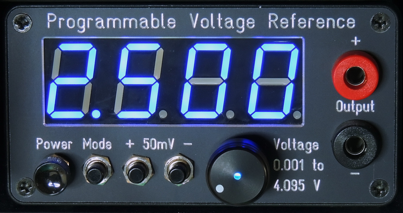
Instead of the four digit seven segment display module used in past versions, the version 3.14 PVR uses a slim 2 line by 16 character OLED display using I2C communications. This allows for additional information to be displayed including Set Voltage, Readback Voltage, Calibration Offset, Mode, and Battery Status.
The output step voltage on the PVR 16 bit DAC is 76.2 microvolts with the 5.000 volt reference. So the voltage output can be set to within 38.1 microvolts of the desired voltage by applying an offset calibration adjustment for each millivolt step setting.
After two months (1,400 hours) of “burn-in”, I calibrated each of the 5,000 one millivolt steps that the PVR can output to within 40 uV of the setpoint, and based on testing over the past few weeks it easily stays well within 50 uV of the set voltage even with temperature changes.
I tested the current output capability at 2.5 volts, and was able to output up to 36 mA before the output sagged 50 µV at the output terminals.
I had the front panel fabricated by Front Panel Express, and used some Pomona 72912 series banana jacks for sheathed plugs with gold plated nickel brass contacts.
I assigned the rotary switch pushbutton to increment the voltage in steps of 250 mV, and added a momentary SPDT switch with center off position to increment and decrement the voltage by 25 mV with each toggle. This allows for quickly setting the voltage in the 5,000 step range using two controls positioned next to each other. The step settings are easily programmable in the software depending on user preference.
The front panel also has SPDT momentary switch for selecting the operational mode. Also included is an On-Off power switch.
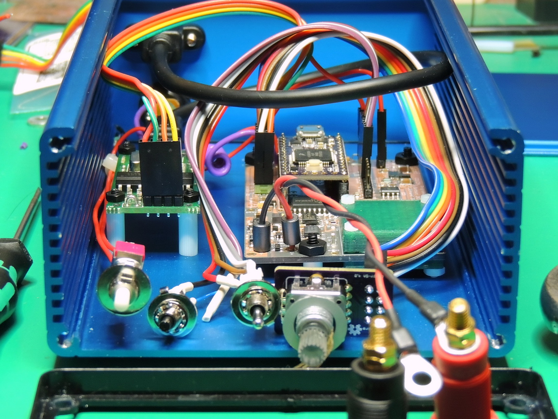
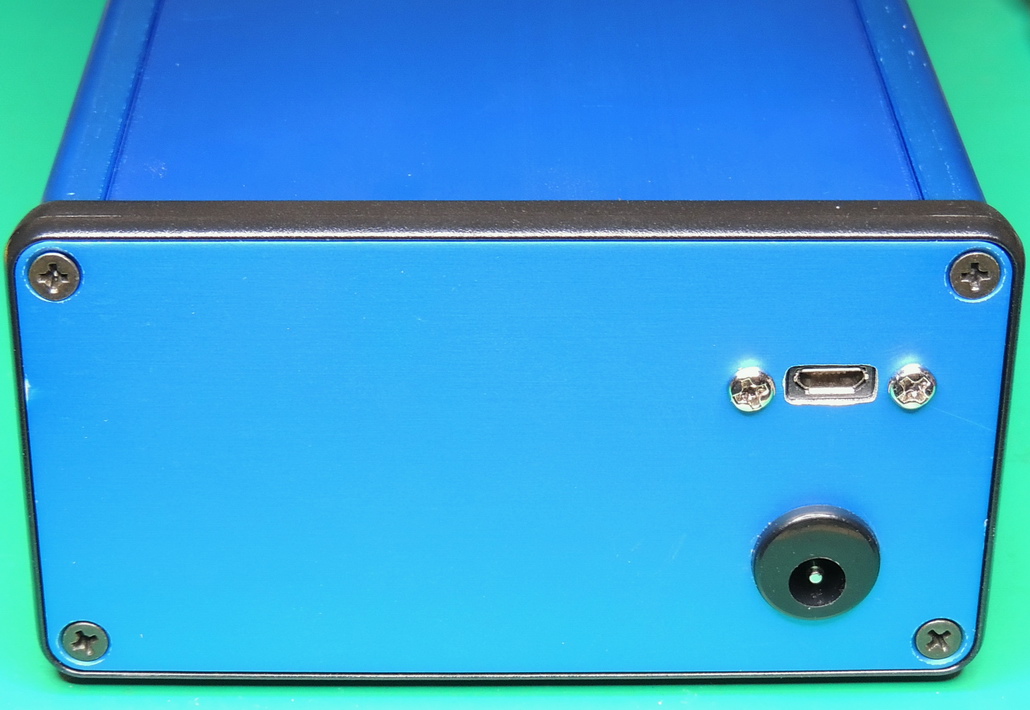
I used an isolated USB to UART serial TTL board by Zeptobit for communications with a host computer. I had ordered several of the isolated USB Zeptobit boards several years ago, and they work well, but now seem to be permanently out-of-stock. I am currently working on my own version of the board, coming soon.
Power is supplied by an external 7.5 volt 300 mA DC power supply connected by a barrel jack and a filtering inductor / capacitor on the back panel.
I am still working on a 2‑cell lithium battery solution for fully isolated use, but it still needs some more work before I will be happy with it.
One of the areas that needs additional work is the software side of the project. It is currently operational, but could be so much better with additional development by people with expertise in that area. I can muddle my way through getting it working, but it is far from elegant.
Some things on the software to-do list are:
- Create a mode for front panel calibration of individual mV steps.
- Provide a way to backup and restore the calibration data using the display EEPROM.
- Download the calibration data to a text file
- Automatic calibration using an external calibrated meter such as a HP 3456A over GPIB
- Mode switching using the front panel mode button
- Auto calibration of the Teensy 3.2 internal ADC to match the PVR’s calibrated output
- Microprocessor and internal ADC sleep mode
- OLED display auto-off setting while leaving the unit powered on
So far the version 3.14 programmable voltage reference has exceeded my expectations. I have already used it on several projects, and I feel that currently it’s only shortcomings are the lack of a internal battery, and some software refinement.
I will also make version 3.15 schematic and board files available, there are no component changes, but I haven’t built a board yet to test that everything is still correct.
EagleCAD 7.7 schematic and board ZIP file for the PVR Version 3.14
EagleCAD sch. and board ZIP file for the PVR Version 3.15 — untested
BOM for PVR 3.14 ZIP file with PDF and Excel files
Teensyduino software sketch for Teensy 3.2 PVR on Github.com
Other files are also hosted on the Github page, including the front panel and 3D files.
Thingiverse .STL files link for 3D printed voltage reference covers
Cover_for_insulated_LTC6655-LS8_Voltage_Reference_board_project_4495146
Links to OSH Park board fabrication for Version 3.14 and Version 3.15
Original design and software by C. Schnarel 2014 https://github.com/uChip/VoltageReferenceProgrammable
Programmable Voltage Reference by G. Christenson 2022 / C.Schnarel 2014 is licensed under a Creative Commons Attribution-ShareAlike 4.0 International License.