출처: https://uptimefab.com/2021/01/11/build-your-own-cnc-controller/
Introduction
In this article I will go through the entire build process for an offline CNC controller that I have made for my 6040 CNC router. Although it is made specifically for my router, most items covered should be applicable for any CNC machine for personal use. The preparation of the enclosure is covered in detail, as well as why I used certain electrical components and I will include any errors I made along the way to hopefully prevent other people from making the same mistakes.
Article last updated: 08 July 2022 (Added 24v LED to Bill Of Materials)
Please Note:
– If you decide to use information from this article or video series, make sure to check your own work. You are responsible for your build, even if you use the components or wiring methods as described in this article. Make sure to have your equipment verified by a licensed electrician before plugging it in.
– Shielded cable going though metal (GX16) plugs: it is preferred to wrap the shielding back around the cable so it comes in contact with the (GX16) connector. No extra pin needed. In that case the connector can be grounded through a metal mounting plate or complete metal housing.
– Consider using a metal enclosure and placing the VFD in a separate metal enclosure, for EMI containment and easier grounding.
– Check power rating for your specific components (VFD and power supply) to see which type of mains connector and fuse you should use. C14 connectors are rated to a maximum of 10amps at 250VAC. One of the possible alternatives is to not use a connector but instead a cable gland and an appropriately rated fuse inside the box or panel mounted fuse holder. Also consider CEE type wall plug if the rating of your wall outlet is not sufficient for your components.
– Using shielded cables for the stepper motors also on the outside of the cabinet reduces the chance EMI issues.
This build is also covered in 3 videos, linked below. In addition to the build instructions in these videos, this article also provides additional information such as software parameters and settings for the DDCS controller and VFD.
Around 5 years ago I bought a 6040 router from the Chinese company YooCNC, who now go by the name OmioCNC. The machine is controlled by MACH3 over a USB connection.
The internal interface board only takes care of the communication with the PC and passes the commands from MACH3 on to the steppers and other components. Although this works fine, I have a preference for using an offline CNC controller. It eliminates the need to have a PC connected to your CNC all the times. Also if the USB connection fails at any point you might be in trouble. I experienced lost steps on the X-axis from time to time, which I hope will also be mitigated with a new controller. Lastly, the wireless controller has some nice functionalities, but there is a significant delay between the input on the MPG and the movements of the axes.

After some searching on Aliexpress I decided to go for the DDCSV3.1 controller. I purchased the 4-axis version since I also wanted to upgrade my router with a rotary axis. Although there are plenty alternatives, I opted for this controller since it appeared simple to use, has all of the functions I need and perhaps most importantly, there is a good manual available for it in English.
Enclosure
The DDCS controller does not fit in the original control box, so I also had to purchase a new enclosure. At first I purchased a plastic one that was only slightly larger than the original controller. However, after trying to fit the components in the new box it quickly became apparent that it is better not to skimp on the size of the enclosure for a DYI controller. A larger enclosure makes your life a lot easier when assembling everything. So I bought yet another enclosure (Famatel) measuring 400 by 500 by 175mm for only €85,-

I prefer a plastic enclosure because it is cheaper and easier to work on than a sheet metal housing.
Salvaging parts from the old Controller
Caution:
Working with mains voltage is dangerous. It can kill you.
Always unplug the device before opening the enclosure.
Since I would not be using the old controller any longer, I took it apart to salvage any parts I could use in the new setup. The original plan was to reuse the Power supply, stepper drivers and VFD and hook all of these up to the new DDCSV controller. This would be a big cost saver and would only require me to buy new buttons and parts for the safety circuit. In the end I also ended up replacing the stepper drivers, but more on that later.

While taking the old controller apart I marked all of the wires and constructed a wiring diagram, to help me understand how everything was connected, so it would be easier to wire the new controller.
Linked below is a PDF file, containing additional information for this build including wiring instructions and software parameters:
The PDF includes:
- Wiring diagram for old YooCNC controller
- Wiring diagram for the new controller as described in this article
- MPG wiring
- Parameter settings for the VFD
- Parameter settings for the DDCS Controller
- GX16 connector wiring (stepper motors)
From the mains plug one of the leads is going to the main power switch. This is connected in series with the E-stop, so you can kill the power to the entire system in case of an emergency. Behind this is a separate power switch for the VFD, so you can choose to leave that off even when the controller is running. The mains power to the VFD goes through an EMI filter to reduce electromagnetic interference. In case you are not familiar with the term VFD: it stands for Variable Frequency Drive. It drives the spindle motor and allows you to control the RPM of the spindle. The Mach3 interface board sends signals to the VDF for both ON/OFF as well as the desired RPM. The Wires connected to U/V/W terminals are going out to the spindle motor. The Mach3 interface board is also providing signals to the stepper drivers. The drivers themselves turn these signals into high current signals that drive the actual stepper motors. The stepper drivers are powered by the 40V power supply. I will go into more detail on how to connect the VFD and stepper drivers further down.
I took out the VFD with the mains cable. Besides the EMI filter, this also includes a ferrite ring a for reducing electromagnetic interference. All of this will be transferred to the new controller. The VFD comes with its own control panel, which can be plugged into the VFD itself or mounted on the outside of the control box to have access while the machine is running.
The drivers are placed between the CNC controller and the stepper motors to drive the motors at the specified current and number of pulses per revolution. More details on the settings for these stepper drivers further down. The only thing left in the old control box is the MACH3 interface card which is no longer needed.
Wiring diagram for the new controller
Refer to the PDF file linked in the section above for the graphical layout. The wiring schematic for the new controller is slightly different compared to the old one. This is mostly due to the addition of a safety circuit. What I did not like on the old controller were the flimsy E-stop button and the switches for the mains power and VFD. These 2 switches were placed directly in line with mains power. This means that if the machine is on and you have a power failure you might end up in a dangerous situation if you forget to turn the machine off before the power comes back on. A more common solution on industrial machines is to use a contactor to switch the mains power. The contactor acts like a sticky relay.

The contactor is engaged by pressing the ON button and disengaged by pressing the OFF button. Both buttons are momentary contacts. The clever bit in this circuit is that the contactor keeps the desired state even after releasing either of these buttons. This is achieved through the use of auxiliary contacts. When the ON button is pressed the contactor closes not only the main contacts for the high power circuit, but it also closes the auxiliary contact. When this happens the contactor is held in place by a current going through the auxiliary contact that it just connected itself. So even after releasing the ON button, the contactor stays engaged. The OFF button is a normally closed contact. When this button is pressed, the circuit is broken and the contactor disengages and also here, stays in that position even after the button is released.
An E-stop button could be wired in series with the OFF button and would act in the same way. If the E-stop is pressed, the contactor disengages and will stay off even if the E-stop is released. You then have to press the ON button as an additional action to turn the machine back on. This is a typical safety feature as releasing the E-stop alone should not be the only action required to turn a machine back on. For my new controller I have an E-stop integrated into the MPG that will make the controller stop all motors and the spindle and will go into E-stop mode, where you cannot do anything until you release the E-stop and then press the reset button. I will wire the separate E-stop in series with the OFF button for the contactor, so this E-stop will actually cut power to the stepper drivers and the VFD. The result is the same as with the software E-stop triggered by the MPG, but in this case the mains power is cut from the components, which is a bit more crude solution, but I believe this adds an additional level of safety. Since the CNC controller is not in the circuit switched by the contactor, the CNC controller will remain on when the E-stop is pressed.
If there is a power failure, the contactor disengages, so when the power comes back on, the machine stays off. If the machine would come back on when the power is restored, this would be a major safety hazard.
Components for new controller
Bill of materials: (Items in bold were added later, in video part 3)
- Enclosure 500x400x175mm – Famatel 39145
- DDCS4 V3.1 CNC Controller, including MPG
- Nowforever VFD E100, 2.2kW
- Stepper Driver – DM556 (Amazon)
- Closed loop Stepper Driver including Nema 23 Stepper Motor Driver 2.2NM Servo Motor 57HSE2.2N+HBS57 Hybrid Closed-loop step motor (Aliexpress)
- Mains Connector K&B 42R321121 (Conrad 736916)
- Mains Power Socket MENNEKES 11011
- 80mm fan. Noctua NF-A8 FLX (12V, this is unfortunately not available in 24V)
- Fan grille LFG80-45 SEPA (Conrad 189516)
- PTFIX 6×2,5 Cable Distribution Block Blue, Phoenix Contact 3273266
- PTFIX 6×2,5 Cable Distribution Block Grey, Phoenix Contact 3273264
- PTFIX Cable Distribution Block Yellow/Green, Phoenix Contact 1091668
- PTFIX NS35 DIN Rail adaptor, Phoenix Contact 3274054
- Relay: Phoenix Contact RIF-1-RPT-LDP-24DC/2X21 – 2903334
- Cable Tie Mount Phoenix Contact 3240706 (WT-BASE LS HF 4) (Conrad 1832324)
- Cable for stepper motors: Lapp 0034704 (LIYCY, flexible, shielded, PVC 4×0.75sq_mm)
- Siemens Mains Switch – 3ld2203-1tl53
- Siemens contactor – 3RT2016-1BB41 (example only: choose type adequate for your system)
- Siemens Surge Suppressor diode 3RT2916-1DG00
- Mean Well 24V Power Supply MDR-20-24
- Mean Well 24V Power Supply LRS-35 (I prefer the MDR-20-24 mentioned above over this one and actually no longer use the LRS-35)
- Mean Well 40V Power Supply S-400-40 (no link available, as this was salvaged from old controller. If I would buy new, I would get a DIN-rail model from the Mean Well NDR series. For NEMA23 motors anything between 24V-48V should work. 48V will provide more torque even at the same current setting compared to 24V, but may not bee needed for smaller CNC machines.)
- RCNUN 15-50V to 12V DC-DC converter (also other models available, as long as input voltage is within input range and output is 12V it should work).
- EATON 230V LED 216563 – m22-LED-230-W (used for VFD switch)
- EATON 12-30V LED 216557 – M22-LED-W (used for the 24V button to turn contactor on/off)
- EATON assembly tool 216402 – m22 ms
- EATON normally open contact block 216376 – m22 k10 (max 6A)
- EATON normally closed contact block 216378 – m22 k01 (max 6A)
- EATON E-Stop 216524 – M22-PV/KC02/IY
- EATON selector switch 216823 – m22 wrlk w
- EATON ON/OFF push button 216700 – M22-DDL-GR-X1-X0
- 4th Axis K11 80mm 3-jaw chuck – Aliexpress, RATTM Motor
I used the power supply that was salvaged from the old controller. It has an output voltage of 40V at a maximum of 10A. This should be sufficient for the 3 NEMA 23 stepper motors which are rated at 3A each. Since I am now also adding a 4th axis to the system it is a bit tighter. But the motors will not all draw their maximum current at the same time. Also, as I understood there is a rule of thumb that states you can use a power supply that is rated to 2/3 of the steppers phase current. So for having 4 motors rated at 3Amps it would require an 8Amp power supply. Unless I run into any stability issues I will keep this power supply.

Two new DIN rail power supplies are used for the DDCS controller and other components. The DDCS requires 2 separate power supplies, one to power the unit and the other for the IO. This reduces the chance of electrical interference.

The new E-stop to replace the flimsy E-stop from the original controller is shown below. It is a standalone unit, so it can be mounted close to the machine. The E-stop contains 2 normally-closed contacts wired in series for redundancy.

The mains switch I bought specifically for this project is ridiculously oversized both in physical dimensions as well as for the specifications. It is rated at 32A, which far more than this little CNC router will ever draw from the grid. So it is a bit over the top, but since I already ordered it and being too heavy and oversized doesn’t matter I decided to use it anyway.

The switches I selected for the new controller are part of the EATON M22 series. The reason I selected these is because they are not very expensive, they have a modular design and there are many different switches available in this series. I used a dual ON/OFF switch with integrated LED and an illuminated Selector switch to turn on the VFD separately. Under the buttons or switches you can place normally open contacts, normally closed contacts, an LED or any combination of these. A separate tool is used to mount the switches to the panel, but you could also tighten them by hand.

The VFD from the old controller is a Nowforever E100 unit. As mentioned earlier this will be reused. For the time being I will leave the panel in the VFD itself instead of placing it on the outside. There is always an option to do that later if needed. This VFD is an older model that is no longer sold.
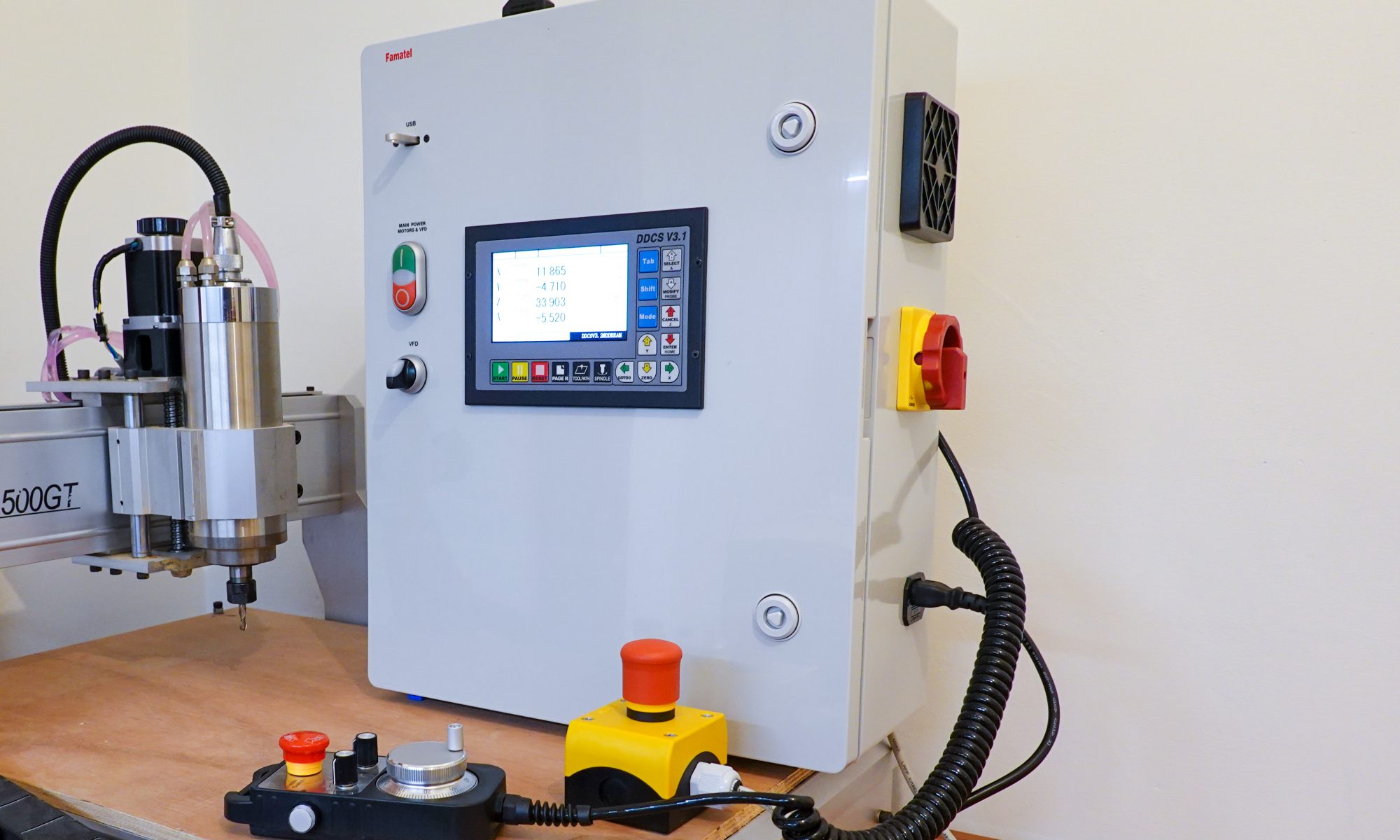
The most important component for this build is the DDCS V3.1 offline CNC controller. It has a compact form factor and a relatively small 5 inch display, which I think is adequate for the application.

This controller is still available, but by the time I completed the build a newer model, the DDCS Expert, is now also available. This unit has some more advanced features, a larger screen and also a larger price tag. It depends whether or not you need the additional features to justify the increase in price. For now, I am happy with the DDCS V3.1.
A number of the buttons have multiple functions based on the menu you are in. On the back there is sort of a break out board that directly mounts to the large sub-D connector. This is where you provide power to the unit and have all of the inputs and outputs. On the bottom there is a separate connector for external start, pause and Estop buttons. These are optional. In the center we have a 15 pin sub-D connector for an MPG.
The final port on the CNC controller is a USB port. A wire is provided with a panel mount USB plug. You can place this in a convenient location and load programs into the controller with a regular USB stick.
This is the MPG for the controller:

In case you are unfamiliar with this term; an MPG is a manual pulse generator. These are used to manually move axes on the machine and typically contain a handwheel and selectors for the axis and step multiplier. This model is very basic, but has all of the necessary functionality for manual jogging of the machine. Since the pulses are directly sent to the CNC controller, the response of the machine to your input on the handwheel feels very direct. With the wireless MPG from the old system with the MACH3 controller and USB break out board, I always felt like there was quite some delay. If you buy this type of controller from Aliexpress you typically have to solder it to a connector yourself.
Stepper drivers
The stepper drivers I salvaged from the old controller have a YOOCNC brand name on them, but there are similar to stepper drivers from many other brands with the same specifications and form factor, so these are likely OEM parts and could be similar to stepper drivers that are just branded differently.

The great thing about these type of drivers is that the settings are printed on the side of the unit, so you don’t have to look for the manual to see how they are configured. The stepper drivers are rated for 5.6Amps, but they are actually set to 2.7Amps, which suits the 3Amp stepper motors used in my CNC router.
Micro stepping is set to 2000 pulses per revolution. A typical stepper motor has 200 steps per revolution. If we divide 2000 by 200, we get 10 microsteps per full step. Microstepping is used to make steppers motors run smoother.
The connections on the driver from left to right:
- 4-pin connector which provides the steps at high current to drive the motor.
- Power input connector: provides power to the stepper driver. The unit can run on anything between 24V and 50V. In this case it is powered by a 40V power supply, which is nicely in between these upper and lower limits.
- Dip switch for configuring the various settings as mentioned earlier.
- Connector to enable or disable the stepper driver. This can be used for example to shut down the unit in case of a failure or an alarm. I will not use this feature. If the pins of the connector are left open, the unit is enabled.
- 4-pin connector. Provides a signal to the stepper driver, which tells the stepper driver how many steps to move the motor and in which direction. This is connected to an output port on the CNC controller, which generates the step signal.
I bought stepper drivers online from Amazon, but you can get them from many online stores including the well-known Chinese sources. Make sure that the drivers you get have screw terminals to avoid having to crimp connectors. I had many issues with the connectors on the other units, so I decided to replace all of them for new ones with the screw terminals.

Layout
Now it was time to figure out a layout for the new controller cabinet, which was harder than I thought. There are many different ways to arrange the components inside the cabinet, each with their own pros and cons. I finally settled on this layout:

It has the stepper drivers at the top of the cabinet, close to the plugs to connect the motors. I placed the VFD on the opposite end of the cabinet since this is the largest source of electromagnetic interference and therefore I would have the lowest chance of it messing up signals to and from the stepper drivers. On the side of the cabinet I placed the power switch , the mains connection plug and 2 inlet ports for air. The inlet ports are located on the opposite side of where the fan is located in an attempt to maximize air flow over the electronic components.
The buttons are placed on the left side of the controller as this felt like the most natural location to me. For example Haas also has their buttons on this side and I am sure there is a good ergonomic reason for it.
A step drill was used to drill out most of the holes. These step drills work very well in thin material.

For the line filter I used self tapping screws. Initially I wanted to use these for most components, since they are easy to install and you can remove them without needing access to the back end such as with a nut and bolt. However, I have less than 10mm of space behind the panel and these screws are too long. In this case I just added some washers to take care of that issue.
For the stepper drives I used regular M4 screws and tapped thread directly into the panel. The panel is quite thin, but since the drivers are not very heavy I think I can get away with this solution.

Since I experienced lost steps with the old controller I decided to use shielded cable wherever possible. For the cables to the stepper motor connectors I used shielded cable with 4 wires of 0.75 mm^2. This should be equivalent to American Wire Gauge Standard (AWG) size 18.


The Mains power connector will be placed on the left side. It will be near the bottom when the cabinet is in its upright orientation. I am planning to hang the controller vertically underneath the table for the CNC router.
For the Air inlets and fan I needed to cut 80mm holes. I used a hole saw for this purpose. The RPM should be low enough to prevent the material from melting. I had stalling issues, so I resorted to applying alternating pressure to make sure the plastic did not get too warm from cutting.

The hole for the DDCSV controller is made primarily with a mini hacksaw. This looks like a lot of work, but in real time it took only around 10 minutes to cut out the hole. Some filing was needed to remove the round corners created by the step drill.

The same approach was used with the rectangular hole for the mains power connector. I was a bit on the safe side with the dimensions when cutting the hole with the hacksaw. It is easier to do some additional filing to increase the size of the pocket then it is to make it smaller.

The Mains Connector is fixed using M3 screws. I am using nylon insert lock nuts everywhere in the controller cabinet, to prevent a metal nut from coming loose and possible cause a short circuit somewhere. The mains connector has an integrated fuse holder. The old CNC controller had an 8A fast acting fuse. I am using the same thing here. 8 Amps at 230V would translate to around 1800 watts. This might seem a bit tight since the spindle is rated at 1500 watts and the power supply at 400 watts, but is has been running without issues with an 8A fuse in the old controller, so I will use that. I would rather have a fuse that blows too soon than one that blows too late
There are ventilation holes in the cabinet: 2 for the inlet and 1 for the outlet of air. Behind the outlet a fan is mounted that will push out warm from the cabinet and at over the inlet ports air vent covers are placed with a basic dust filter. This is a very coarse filter, but at least it will keep out larger dust particles.

Connecting the fan
The fan on the old controller was very loud, and I like to keep the noise level down as much as possible when the router is not in operation. So I went for an 80 mm Noctua fan (this needs a 12V power supply or 24V to 12V step down converter). It has all kinds of features to reduce the noise level, including rubber mounts and specially designed fan blades to prevent turbulent air flow. It comes with 3 different cables. Depending on which cable you select you can run the fan on low, medium or high speed. With of course the highest speed delivering the highest air flow, but also being the least quiet. I ended up going for the low setting. It seems to generate enough air flow for this application. I am going with gut feeling for now. If I find out later that the air exhausted from the cabinet is too hot I can always go to a higher setting.
I am not using the rubber fan mounts in this case, because where the fan is located they would be hard to install. The use of screws does not add any significant vibrations or noise from what I can tell.
I am connecting the fan to the small 24V power supply. Since I cut one of the adaptor cables that I would not need in half and placed some connectors onto the ends, so I could hook it up to the power supply. With this setup I can connect the fan directly for full power or insert one of the low noise adaptor cables in between, just by unplugging the connector. The fan has 3 wires coming out of it: red and black for power and the yellow wire for RPM control. I am not using this feature, so I cut off the yellow wire.

For each adaptor the sound level is reduced by roughly 2 decibels, for a total of 4 decibels when using the lowest speed adaptor. Since a doubling of sound energy is 3 decibels, the sound reduction by using the adaptors is very significant.
Pictured below is the small 24V power supply I bought specifically for the safety circuit. It is low power, since it is only used to activate the contactor. This will be powered on directly by the mains switch, so it can actually be used to power the contactor.

The form factor of this is much nicer in my opinion than that of the other small power supply. It is smaller, you can’t touch the contacts and it mounts to a DIN-rail. In hindsight I also should have bought a DIN-rail version for the other small power supply, but since that was already fixed in place I decided to leave it the way it was. The DDCS is on a separate power supply since I want to prevent any voltage surge when disengaging the contactor to impact the electronics in the DDCS. Another (probably better) solution is to add surge protection to the contactor. I found a video dedicated to this topic, which explains the phenomenon and different mitigations in detail.
https://www.youtube.com/watch?v=Ij0B-2gxH7w
I wanted to use flexible wire for the connections between the various high voltage components. This is probably not best practice, but I salvaged wire from a used 230V volts power cord. This means I am using brown and blue wires for the high voltage connections. This is not according to EN standards, but keep in mind this is a hobby project and not intended for commercial use. As far as I know you should be using black for mains voltage, but since I am already using black as the neutral wire for the low power circuits I did not want to get the two mixed up. So please don’t use this article to try and figure out what color of wire you should be using for you project, as what you are seeing here is not according to any standard.
I used the appropriate crimp connectors to be able to connect the wires to the mains connector and other components.
I have tried to crimp connectors to the wires for the stepper drives that I salvaged from the old controllers. Unfortunately they did not have screw terminals for the wires, which is far easier when you are making your own controller. I made several attempts to make connectors that had reliable connections, but had one failure after another. It might be that I am using the wrong pliers of just lack of skill, but I could not get the connectors to firmly grip the wires. Before realizing this, I actually completed all of the wires and even started installing them in the cabinet. I was able to pull the wires manually from the connectors fairly easily. Therefore I decided to go for another solution. Since you can buy stepper drivers for less than 20 euros I ordered some new ones and started the wiring process again. The new stepper drivers have screw terminal blocks which can also be removed if necessary. In the picture below the stepper drivers are shown after connecting all wires, with from left to right: stepper signal cable, 40V power and the wires leading to the stepper motors.

USB cable
The USB plug will be placed in the top left of the front panel. The cable gives you the freedom to place the USB connector anywhere you like. Since the connector is rectangular in shape this again required some cutting and filing.

MPG cable
For the MPG a cable is needed that runs from the back of the controller to a connector on the outside of the cabinet. In this case the top panel. Unfortunately this does not come supplied with the controller. I opted for a 15 pin sub-D connector, that I manually soldered to the cable. And of course some more cutting and filing. I would have liked to have mounted the connector to the panel from the inside, but the plastic housing is quite thick, so it had to be mounted on the outside. Less pretty, but it works.
For the flat cable I printed out some cable clamp, which I designed in Fusion 360. It’s based on a design I found on Thingiverse, but now that I want to reference it I can’t find it anymore between the many designs people have posted. I have uploaded my own version of this clip on grabCAD. It can be downloaded using the following link:
https://grabcad.com/library/flat-cable-clip-1

In a local electronics store I also bought a nice connector that makes a connection with each wire lead by cutting into it. Unfortunately it turned out not to be so simple. It just did not seem to close properly. At closer inspection it turned out that the connector had a different pitch than the flat cable I was using. Here you can see it compared to some old flat cable I had laying around. To prevent another trip into town just for a new connector, I ended up soldering this side as well.
In the old situation my VFD is controlled through the MACH3 breakout board. I will be controlling the VFD in the same way , using the 0-10V signal input to control spindle speed. On both the DDCS controller and the VFD I am indicating that at 0V the spindle should stop and at 10V the spindle speed should be at the maximum RPM for the spindle, in this case 24.000RPM. Any other voltage in between will set the spindle to the corresponding spindle speed. For example, if my NC program has a spindle speed command for 12.000 RPM, the DDCS controller will output 5V and the VFD will then know it has to control the spindle speed to be 12.000RPM.
There is also a start-stop signal connected to the VFD, so you can start the spindle from within your NC program with the M03 command. The controller also offers the possibility to change spindle direction, but since I only use the clockwise spindle direction, just being able to turn it on or off is fine.
The connections are as follows:

- R,S: 230V
- U,V,W: Spindle
- COM: this is connected to the negative common terminal on the DDSCV controller. This is to make sure the negative common connection is at the same voltage level between the controller and the VFD instead of being a “floating” voltage.
- AIN1: 0-10V input for controlling spindle speed. Make sure the AIN1 jumper to the left of the terminal block is set to 10V, NOT the 20mA setting.
- X1: turn spindle on or off. Open is off, connected to ground is on.
I also went through all of the parameter settings on the VFD but did not change any of them. In the PDF file linked in the top of the article all of the parameter settings are listed, for anyone that is interested.
PTFIX distribution blocks
When all of the wiring was completed I was not quite happy with the combination of cheap terminal blocks and separate wire connectors. Therefore I replaced these with 2 sets of PTFIX distribution blocks. 1 set connected to the main power switch and the other set that is only live when the contactor in engaged. I chose the PTFIX series because they are compact and very easy to use. The individual blocks can be snapped together. The set of blocks can then be mounted onto a DIN rail fixture by just sliding them in.

There are also individual DIN rail fixtures available if you want to have the blocks mounted in parallel to the DIN rail but these take up more space and require the use of conductors as well as end caps.
It is good to use cable ducts between the components, to get the cleanest look and easiest installation of the wires, but this would require an even larger enclosure, so I just bundled the wires wherever possible.
Probe
A tool probe to measure the tool length can also be used with the DDCS controller. I am using the probe that came with my router.
The probe is connected to pins 1 and 4 on the DDCS controller. There is a separate screen available on the DDCS controller to monitor the status of the inputs and outputs. I used this to verify if the probe was connected properly.

The tool probe has a clamp that attaches to the end mill. When the tool comes down and touches the base of the probe, it makes an electrical connection. The DDCS controller has a built in probe function to measure tool length. This routine lowers the Z-axis until the tool makes contact and then sets the top of your stock material to zero. You can enter the thickness of your sensor into the controller, so it automatically adds this value to the measurement. Refer to the attached PDF for the probe settings.
4th Axis
Since I have had the router, I have always wanted to upgrade it with a 4th axis, so I included that as well into this project. So I added a 4th stepper driver and connected this to the DDCS controller. The wiring is exactly the same as for the X,Y and Z axes. The software parameter settings are included in the PDF file.

I bought a typical 4th axis set from aliexpress. The cheap kind with a belt drive. I hope this provides enough rigidity for cutting wood and plastics, but I have not actually used it yet since Fusion360 recently disabled multi axis machining for the free license. My plan is to program this with FreeCAD. To be continued.
I made a cable for the 4th axis out of the same shielded wire that I used to connect the stepper drivers. To transfer to cable through the enclosure I used the same GX16 connectors as for the other axes.
Spindle RPM check
To verify if the spindle RPM is in line with the programmed speed I measured the spindle speed at various settings across the range between 1.000 and 24.000 RPM. As you can see in the graph the spindle speed behaves very nicely and is perfectly lineair except in the lower range. This can be tweaked with VFD parameters, but for my purpose this is definitely acceptable.

E-stop
I mounted an external E-stop to the controller. It is a very sturdy E-stop, with 2 normally closed switches, which are connected in series for redundancy. So only one of the switches has to function for the E-stop to work. It is wired in such a way that it will disengage the contactor and thereby cut power to the motors and VFD.

When the E-stop is pressed the stepper motors stop almost instantly and the spindle slowly coasts to a stop as it is no longer powered.
The E-stop button on the MPG works a bit different. This puts the controller in E-stop mode. The response is faster in this case. The steppers stop immediately and the spindle is actively ramped down by the VFD, so this also stops faster. As a third benefit, the controller actually knows there is an E-stop condition, so it pauses the program, whereas the program keeps running with the external E-stop even though the machine itself stops.
I think both solutions have their benefits, but my preference is for the software E-stop. It is possible to re-wire the external E-stop to an input on the controller. This should give similar results to the E-stop on the MPG.

So far, I have ran a few test programs and everything seems to work.
If you have any questions on this build, please let me know in the comments section below.
Robin